From OSB to drywall, there’s a heavy-duty path to insulated performance.
Insulation (such as fiberglass, rock wool, or cellulose) need a complete air barrier on all six sides. This ensures the thermal control layer works effectively, since air can flow through it.
Think of the difference outdoors on a cold windy day with a sweater and jacket made of a water repellent fabric: Without the jacket, the cold wind easily passes through the sweater and mitigates its thermal resistance.
In contrast, with the jacket functioning as an air impervious control layer, air flow through the sweater is blocked, resulting in much more effective thermal protection. It’s the same with buildings. Note that some types of insulation are air impervious (e.g., closed-cell foam, foil-faced rigid insulation) and can function as the air and thermal control layers.
Exterior weather resistance barrier (think house wrap, building paper, liquid membrane, and roofing felts) is often mistaken as the primary air barrier on the exterior of homes. Yes, such barriers do resist air flow, but this function is already provided by traditional exterior sheathing materials (e.g., oriented strand board [OSB], plywood, rigid insulation boards).
To ensure a complete air control layer, sheathing needs to be sealed at all joints, gaps where sheathing is attached to framing, and penetrations. Thus, the weather-resistant barrier primarily functions as the water control layer for shedding bulk moisture that gets past the cladding or roofing. And water gets past all claddings and roofing. They also need to provide adequate vapor flow for wall and roof assemblies to dry to the outdoors.
On the interior, the primary air barrier is the drywall. The joints are filled with spackle and taped to form a complete air barrier. In addition, the drywall needs to be sealed to the top and bottom plates adjoining unconditioned attics or basements, and at all penetrations (outlets, switches, and duct boots).
The dropped framing detail adjoining a vented attic and exterior wall shown in Figure 1 demonstrates how the absence of a complete air barrier contributes to thermal bypass and moisture risk.
As shown here, the air barrier below the attic insulation and at the exterior wall (e.g., drywall) is often missing in older construction because it is difficult to install once framed.
In the winter condition shown, the exterior and attic are at the same sub-freezing temperature and the house is heated to 70 degrees Fahrenheit. The space in the dropped ceiling would quickly assume the 70 degrees Fahrenheit room temperature (not shown in the diagram) since the drywall covering the soffit provides little thermal resistance. Where there is a pressure difference between the attic and home (e.g., windy day), there will be driving forces from more to less air pressure, and more to less heat.
Since fibrous insulation resists thermal flow but not air flow, the driving forces would result in a thermal flow between the dropped ceiling and attic until some balance point is reached. This is shown in the diagram as 45 degrees Fahrenheit, the mid-point of the temperature difference across the dropped ceiling and attic. This results in a cold surface temperature at the dropped ceiling drywall.
Also note that if fibrous insulation is used in the walls, the same driving forces could result in air flow through the wall insulation to the cold exterior sheathing where condensation and moisture damage can occur.
In a home missing air barriers at dropped ceilings, a wintertime infrared image shows light images are warm and dark surfaces are cold. It will also show extensive thermal bypass through the attic insulation resulting in extensive cold surfaces.
In the summer, this thermal bypass will work in reverse and lead to excessively hot surface temperatures at the dropped ceilings. This can cause significant comfort issues due to the disproportionate impact mean radiant surface temperatures have on comfort relative to ambient temperature.
Figure 3 shows a solution to the dropped ceiling air barrier detail, where drywall has been installed at the ceiling and wall adjoining an unconditioned attic and garage ahead of the soffit framing. Note that all seams are fully taped and spackled, and edges sealed for a complete air control layer. This will mitigate the type of thermal bypass problems that were noted earlier.
Table 1. Comprehensive Air Barrier Details. Source: U.S. EPA
A section through the whole house should pass a red line test where the exterior and interior air barrier can each be drawn continuously without lifting the pen. An example of this red line test is shown in Figure 4 for two homes: one with a vented attic and one with an unvented attic. The choice between these two roof insulation options has a significant impact on cost and performance.
In the unvented attic, the interior drywall ceiling serves as the only air barrier at the attic/ceiling interface with the air barrier missing at the top side of the insulation. Therefore, this is not a six-sided assembly with nearly half of the ceiling insulation surface area exposed to the attic (assuming wind baffles or blocking at the eaves between rafters).
Since fibrous insulation is typically used for ceiling insulation, this top layer is exposed to air flow. Thus, any driving forces in the attic due to wind, excessive temperatures, and high humidity can lead to more to less air, heat, and moisture flow through the attic insulation.
In addition, fibrous insulation in the attic is subject to compression and reduced performance over time, as it accumulates moisture and maintenance work involves workers in the attic.
I assume code insulation requirements are much greater for attics than walls to account for the missing topside air barrier and more egregious attic summer temperatures.
A six-sided assembly can easily be implemented in most climates, with an unvented attic insulated at the slope with spray foam or structural insulated panels. This dramatically improves the effectiveness of the roof insulation albeit with added volume of conditioned or semi-conditioned space. I personally don’t believe that codes and modeling software adequately recognize the thermal performance benefit with this option.
In addition, an unvented attic saves significant cost by eliminating the need for all the air leakage and air barrier details at the attic/ceiling interface, as well as attic venting (e.g., soffit vents, gable vents, ridge vents).
As a bonus, unvented attics provide enhanced structural performance, greater resistance to wildfires and heavy winds, and extra conditioned or semi-conditioned space that can be used for additional rooms, storage, and heating and cooling systems. Thus, unvented attics fix the missing air barrier problem while also providing impressive benefits. This is the type of extra value targeted by Housing 2.0 best practices for optimizing the user experience.
Want to learn more building science best practices? Join my Housing 2.0 program. In the program, I share with you more than 19 strategies and 150 best practices that can help you extract 25%-65% cost savings for every new home built! The next workshop session starts May 26. Due to the generosity of our sponsors, Mitsubishi Electric , Westlake Royal Building Products and Schneider Electric , we are now offering the Series 2 and Series 3 workshops free.
Sam Rashkin’s two-decade career as a licensed architect includes serving on national steering committees for the U.S. Green Building Council (USGBC)’s LEED for Homes, Green Builder Media’s Green Builder Guidelines, the Environmental Protection Agency (EPA)’s WaterSense label, and EPA’s Indoor airPLUS label. He has partnered with Green Builder Media to develop the Housing 2.0 program , which empowers building professionals to design and construct higher-performance, healthier and more-sustainable homes at a fraction of the cost.


The Missing Air Barrier
From OSB to drywall, there’s a heavy-duty path to insulated performance.
Insulation (such as fiberglass, rock wool, or cellulose) need a complete air barrier on all six sides. This ensures the thermal control layer works effectively, since air can flow through it.
Think of the difference outdoors on a cold windy day with a sweater and jacket made of a water repellent fabric: Without the jacket, the cold wind easily passes through the sweater and mitigates its thermal resistance.
In contrast, with the jacket functioning as an air impervious control layer, air flow through the sweater is blocked, resulting in much more effective thermal protection. It’s the same with buildings. Note that some types of insulation are air impervious (e.g., closed-cell foam, foil-faced rigid insulation) and can function as the air and thermal control layers.
Exterior weather resistance barrier (think house wrap, building paper, liquid membrane, and roofing felts) is often mistaken as the primary air barrier on the exterior of homes. Yes, such barriers do resist air flow, but this function is already provided by traditional exterior sheathing materials (e.g., oriented strand board [OSB], plywood, rigid insulation boards).
To ensure a complete air control layer, sheathing needs to be sealed at all joints, gaps where sheathing is attached to framing, and penetrations. Thus, the weather-resistant barrier primarily functions as the water control layer for shedding bulk moisture that gets past the cladding or roofing. And water gets past all claddings and roofing. They also need to provide adequate vapor flow for wall and roof assemblies to dry to the outdoors.
On the interior, the primary air barrier is the drywall. The joints are filled with spackle and taped to form a complete air barrier. In addition, the drywall needs to be sealed to the top and bottom plates adjoining unconditioned attics or basements, and at all penetrations (outlets, switches, and duct boots).
As shown here, the air barrier below the attic insulation and at the exterior wall (e.g., drywall) is often missing in older construction because it is difficult to install once framed.
In the winter condition shown, the exterior and attic are at the same sub-freezing temperature and the house is heated to 70 degrees Fahrenheit. The space in the dropped ceiling would quickly assume the 70 degrees Fahrenheit room temperature (not shown in the diagram) since the drywall covering the soffit provides little thermal resistance. Where there is a pressure difference between the attic and home (e.g., windy day), there will be driving forces from more to less air pressure, and more to less heat.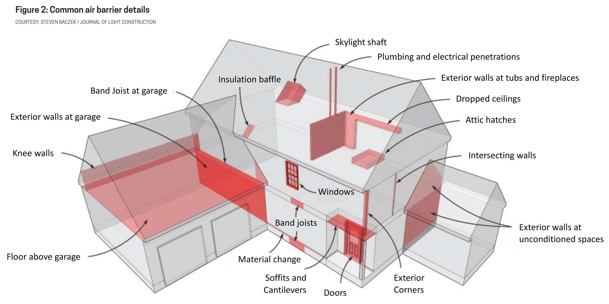
Since fibrous insulation resists thermal flow but not air flow, the driving forces would result in a thermal flow between the dropped ceiling and attic until some balance point is reached. This is shown in the diagram as 45 degrees Fahrenheit, the mid-point of the temperature difference across the dropped ceiling and attic. This results in a cold surface temperature at the dropped ceiling drywall.
Also note that if fibrous insulation is used in the walls, the same driving forces could result in air flow through the wall insulation to the cold exterior sheathing where condensation and moisture damage can occur.
In a home missing air barriers at dropped ceilings, a wintertime infrared image shows light images are warm and dark surfaces are cold. It will also show extensive thermal bypass through the attic insulation resulting in extensive cold surfaces.
In the summer, this thermal bypass will work in reverse and lead to excessively hot surface temperatures at the dropped ceilings. This can cause significant comfort issues due to the disproportionate impact mean radiant surface temperatures have on comfort relative to ambient temperature.
A complete air barrier requires a wide range of special details that occur in home construction as shown in Table 1. An excellent reference for these details is the “ENERGY STAR Qualified Home Thermal Bypass Checklist Guide.”
Table 1. Comprehensive Air Barrier Details. Source: U.S. EPA
In the unvented attic, the interior drywall ceiling serves as the only air barrier at the attic/ceiling interface with the air barrier missing at the top side of the insulation. Therefore, this is not a six-sided assembly with nearly half of the ceiling insulation surface area exposed to the attic (assuming wind baffles or blocking at the eaves between rafters).
Since fibrous insulation is typically used for ceiling insulation, this top layer is exposed to air flow. Thus, any driving forces in the attic due to wind, excessive temperatures, and high humidity can lead to more to less air, heat, and moisture flow through the attic insulation.
In addition, fibrous insulation in the attic is subject to compression and reduced performance over time, as it accumulates moisture and maintenance work involves workers in the attic.
I assume code insulation requirements are much greater for attics than walls to account for the missing topside air barrier and more egregious attic summer temperatures.
A six-sided assembly can easily be implemented in most climates, with an unvented attic insulated at the slope with spray foam or structural insulated panels. This dramatically improves the effectiveness of the roof insulation albeit with added volume of conditioned or semi-conditioned space. I personally don’t believe that codes and modeling software adequately recognize the thermal performance benefit with this option.
In addition, an unvented attic saves significant cost by eliminating the need for all the air leakage and air barrier details at the attic/ceiling interface, as well as attic venting (e.g., soffit vents, gable vents, ridge vents).
As a bonus, unvented attics provide enhanced structural performance, greater resistance to wildfires and heavy winds, and extra conditioned or semi-conditioned space that can be used for additional rooms, storage, and heating and cooling systems. Thus, unvented attics fix the missing air barrier problem while also providing impressive benefits. This is the type of extra value targeted by Housing 2.0 best practices for optimizing the user experience.
Want to learn more building science best practices? Join my Housing 2.0 program. In the program, I share with you more than 19 strategies and 150 best practices that can help you extract 25%-65% cost savings for every new home built! The next workshop session starts May 26. Due to the generosity of our sponsors, Mitsubishi Electric , Westlake Royal Building Products and Schneider Electric , we are now offering the Series 2 and Series 3 workshops free.
By Sam Rashkin
Sam Rashkin’s two-decade career as a licensed architect includes serving on national steering committees for the U.S. Green Building Council (USGBC)’s LEED for Homes, Green Builder Media’s Green Builder Guidelines, the Environmental Protection Agency (EPA)’s WaterSense label, and EPA’s Indoor airPLUS label. He has partnered with Green Builder Media to develop the Housing 2.0 program , which empowers building professionals to design and construct higher-performance, healthier and more-sustainable homes at a fraction of the cost.Also Read